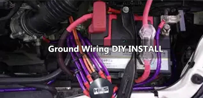
Before we delve deeper into the tutorial. Let us look at the benefits of a ground wire or big 3 kit. Firstly, you shouldn't be expecting substantial horsepower gains. You can rather expect a smoother idling engine and an improved throttle response. Brighter headlights and cleaner audio has also been experienced by some diyers.
Some guys even claim that the ground wires prevent static shocks when getting out of the car.
Also, We checked the voltage differences beforehand at planned grounding points using a recently calibrated Fluke 87 multimeter.
Planning the Grounding Points
The DIY ground wire system we will make and install, dubbed the "Ill save money on mechanic bills," consists of 4 wires connecting 5 points.
Body (A) > Head (B) > Coil Pack (C) > Battery Negative (D) > Body (E)
You can choose your own ground points as well, but you will be on your own with that. Choose your grounding big 3 points wisely and at your own risk. In case you decide to choose your own ground points, get some string and measure those points. Measure with strings to figure out how exactly much wire is needed. Similarly different gauge wires can be used. Most aftermarket kits are 4-gauge.
For the "Ill save money on mechanic bills kit" you will need:
- Wire cutters/crimper/scissors/pliers
- Socket wrench (10 mm socket)
- 7' of-8 gauge speaker wire (81" for the kit, 3" left over)
- 10 pieces of 8-gauge ring connectors (5/16" hole)
- About 1' of heat shrink tubing that will fit over the crimped ring connector and wire
- A lighter (for the heatshrink)
Preparing the Ground Wires for your Big 3 Update:
- Cut the wires into the lengths needed.
- Once You have finished cutting the wires , use a pair of wire strippers (or scissors) to strip about 1/2" off of the wire insulation to make way for the ring connector. Try not to cut the copper bit of the wires. If a few strands end up getting cut, it's okay. However, if half the strands are wasted, you will have to do it again. There should be enough slack in the wire for mess ups. To prevent fraying twist the wire strands into a rope. Repeat this step for the other side of the wire.
- Once you have stripped off the insulation, slide on 2 pieces of heat-shrink on to the wires. The length of the heat-shrink should be sufficient to cover (and overlap) the crimp-able area of the ring connectors. With the heat-shrink out of the way, slide on the ring connector onto the wire firmly.
- Using a pair of wire crimpers (or stripper/pliers), crimp the ring connector, and then follow through until the whole connector is crimped. Make sure that the 2 pieces of heat-shrink are still tight on the wire, and then repeat this step for the other side. Double-check the crimps for tightness. Refrain from pulling on the ring-connectors. Just make sure the crimps are tight by re-crimping them. Slide the heat-shrink onto the crimped area of the ring connector. Make sure the hole is not covered, and then use the lighter to activate the heat-shrink.Repeat steps 2 to 4 until for all four wires . Once all of them are done, you should have a kit.
With the kit made, onto the installation!
Weave Wire 2 through the wiring loom and s unscrew the last coil bolt putting the end of the Wire 2 and the beginning of Wire 3 together. Screw the coil bolt back on.
Ground Wiring Kit DIY Installation(wiring instructions)
To make things less complicated, the wires will be named:Wire 1:
15" Body (A) to Head (B)Wire 2:
22" Head (B) to Coil Pack (C)Wire 3:
27" Coil Pack (C) to Battery Negative (D)Wire 4 :
17" Battery Negative (D) to Body (E)Ground Wiring Kit Installation Step by Step Tutorial:
Step 1:
Use the 10mm socket wrench to unbolt the nuts on your engines valve cover. Remove the valve cover completely.
Step 2:
We are ready for the installation of our Big 3 kit now.We will start from the left side of the engine.Simple unscrew the bolts on the bracket that holds the A/C line. Put one ring connector on Wire 1 through the bolt then screw it back in firmly.

That machine is nice and clean
ReplyDeleteThat machine is nice and clean
ReplyDelete